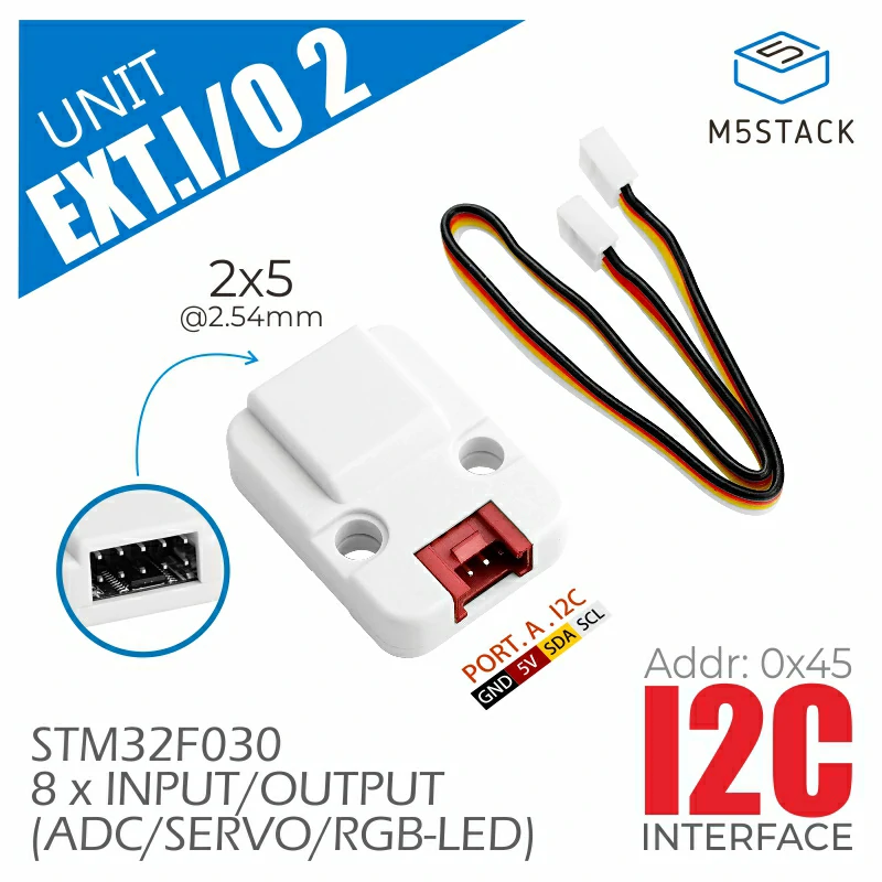
EXTIO2 Unit
EXT.IO2 是一款 IO 扩展 UNIT,基于 STM32F030 主控制器,采用 I2C 通信接口,提供 8 路 IO 扩展。每路 IO 均支持独立配置为数字 I/O、ADC、SERVO 控制、RGB LED 控制等模式。支持配置设备 I2C 地址,这意味着用户可以在同一 I2C BUS 上挂载多个 EXT.IO2 UNIT,以扩展更多 IO 资源。适用于多路数字/模拟信号采集,以及照明 / 舵机控制等应用场景。
支持以下产品:
MicroPython 应用示例
 1# SPDX-FileCopyrightText: 2024 M5Stack Technology CO LTD
 2#
 3# SPDX-License-Identifier: MIT
 4
 5import os, sys, io
 6import M5
 7from M5 import *
 8from hardware import *
 9from unit import EXTIO2Unit
10
11
12title0 = None
13label0 = None
14i2c0 = None
15extio2_0 = None
16
17
18def setup():
19    global title0, label0, i2c0, extio2_0
20
21    M5.begin()
22    Widgets.fillScreen(0x222222)
23    title0 = Widgets.Title(
24        "ExtIO2Unit Core2 Example", 3, 0xFFFFFF, 0x0000FF, Widgets.FONTS.DejaVu18
25    )
26    label0 = Widgets.Label("IO6 State:", 2, 116, 1.0, 0xFFFFFF, 0x222222, Widgets.FONTS.DejaVu18)
27
28    i2c0 = I2C(0, scl=Pin(33), sda=Pin(32), freq=100000)
29    extio2_0 = EXTIO2Unit(i2c0)
30    extio2_0.set_config_mode(0, 1)
31    extio2_0.set_config_mode(6, 2)
32    extio2_0.set_config_mode(3, 4)
33    extio2_0.write_rgb_led(3, 0xFF0000)
34
35
36def loop():
37    global title0, label0, i2c0, extio2_0
38    M5.update()
39    label0.setText(str((str("IO6 State:") + str((extio2_0.read_adc12_pin(0))))))
40
41
42if __name__ == "__main__":
43    try:
44        setup()
45        while True:
46            loop()
47    except (Exception, KeyboardInterrupt) as e:
48        try:
49            from utility import print_error_msg
50
51            print_error_msg(e)
52        except ImportError:
53            print("please update to latest firmware")
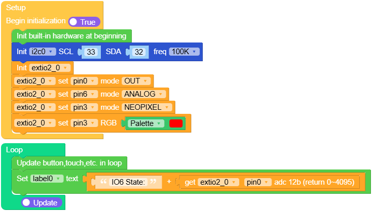
UiFlow2 应用示例
class EXTIO2Unit
Constructors

Methods
- EXTIO2Unit.set_config_mode(id, mode)
为特定通道设置配置模式。
- 参数:
id (int) – 用于设置模式的通道 ID。
mode – 要设置的模式,由 EXTIO2Unit 定义。可以是 0、1、2、3 或 4。
UIFLOW2:

- EXTIO2Unit.write_output_pin(id, value)
将值写入 EXTIO2Unit 的输出引脚。
- 参数:
id (int) – 要写入数值的引脚 ID。
value – 要写入的值,可以是 0 或 1。
UIFLOW2:

- EXTIO2Unit.write_servo_angle(id, angle)
向连接到 EXTIO2Unit 的舵机写入一个角度。
UIFLOW2:

- EXTIO2Unit.write_servo_pulse(id, pulse)
将脉冲宽度写入连接到 EXTIO2Unit 的舵机。
UIFLOW2:

- EXTIO2Unit.write_rgb_led(id, value)
向 NeoPixel LED 写入 RGB 颜色值。
- 参数:
id (int) – 要设置颜色的 NeoPixel ID。
value – 要设置的 RGB 值,以 24 位整数表示。
UIFLOW2:

- EXTIO2Unit.set_address(address)
为 EXTIO2Unit 设置 I2C 地址。
- 参数:
address (int) – 要为单元设置的新 I2C 地址。
UIFLOW2: